


Slave characteristics
Certified AS-Interface slave with two input functions and one dimmable output to accept a pluggable LED with T5,5K socket
Output with short-circuit and overload protection
Up to max. 62 slaves can be connected to one single AS-Interface cable
Input data ports D2 and D3
The LED can be dimmed in 4 steps while toggling between two brightness levels is possible via the outputs D0 and D1
Same size as the standard contact blocks of the "A...“ type series - Failure-safe operation even under extreme environmental conditions (e.g. welding plants, frequency converters)
Combination with 2- and 3-position selector and key switches is possible
AS-Interface profile S-B.A.E (extended address mode)
Output data ports D0 and D1
Easy connection via 2-pole IDC connector
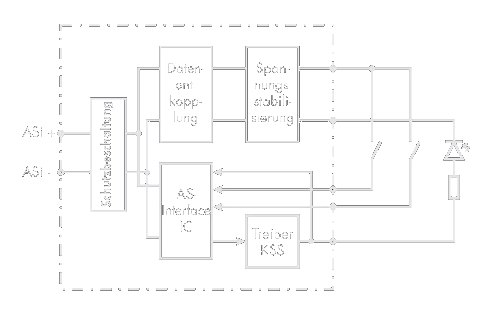
Blockschaltbild
Data bits of the outputs and inputs
General

Pushbutton head

Selector/key switch,
with 2 positions (one-piece plunger)

Selector/key switch,
with 3 positions (2-piece plunger)

Note
For the use of 2-position selector and key switches with 2 plungers: As the switch head and ASI slave can be snapped together turned by 90°, the following basic positions must be observed for a clear assignment of the input bits (DI2, DI3):
ASI slave connections upward
Locating lug upward

Norms and standards
AS-Interface, the standard of the lower field level, complies with the European norm EN 50295 and the worl standard IEC 62026-2.
Certification and AS-Interface Logo: The reliable function and failure immunity of the SCHLEGEL slaves were tested by an authorised laboratory. All certified products are bearing the AS-Interface Certification Logo.
AS-Interface specification, version 2.11, revision 1
CE
UL
CSA
Connection of slaves
The slaves are connected (by insulation piercing) to the flexible equipment wire via a 2-pole, reverse polarity protected connector (3.96 mm) with lock mechanism and strain relief.
Cable requirements
The connecting cable must meet the following requirements:
Colour coding: brown: ASI+ / blue: ASI-
Insulation: medium hard PVC insulation, suitable for insulation piercing (IDC technology)
Single conductor size: AWG 18 (0.8...1.0 mm²)
Outer diameter: min 1.0, max. 2.28 mm
Operating temperature: -30°C <= T <= 90°C
Approvals: VDE 0881 / MIL-W-1687 8D / UL 1007 or 1061 or 1095
Connection to AS-Interface profile cable
Depending on the case of application, there are different possibilities to connect a double-core flexible wire (AWG18) to the AS-Interface profile cable.
Addressing of slaves
Each AS-Interface slave gets an individual address allowing the master to identify it. Possible addresses are from 1A to 31A and 1B to 31B (A/B slaves, version 2.1). The address 0 has a special function. Depending on the technology that is used, addressing of the slaves is done either before or after the assembly.
Addressing possibilities
The slaves are connected (by insulation piercing) to the flexible equipment wire via a 2-pole, reverse polarity protected connector (3.96 mm) with lock mechanism and strain relief.
1
Addressing cable + addressing device: The easiest way to assign the addresses is to use a hand-held addressing device which is directly connected to the slave via the SCHLEGEL addressing cable "ASI_PK500M12". The arrangement of the devices at the AS-Interface cable is independent from the assignment of the addresses.
2
Addressing with AS-Interface controller / PLC Various producers of controllers/PLC support the following addressing possibilities
:
• Automatic addressing of the complete system
• Individual addressing via the connected master
• Individual addressing via PC with implemented software
Notes
Avoid double addressing!
A/B slaves (V2.1) cannot utilise the 4th output data bit because it is used to change over to the B slaves.
A/B can be operated with AS-Interface 2.0 masters, provided the following is strictly observed:
• Only "A" addresses are used
• The 4th data bit must permanently be "0"
• The 4th parameter bit must be "1"